Rebuilding this ski-binding clip as editable CAD, from photos alone. The black receiver was the hard half — it took 28 revisions.
Reading a Ski-Skin Connector
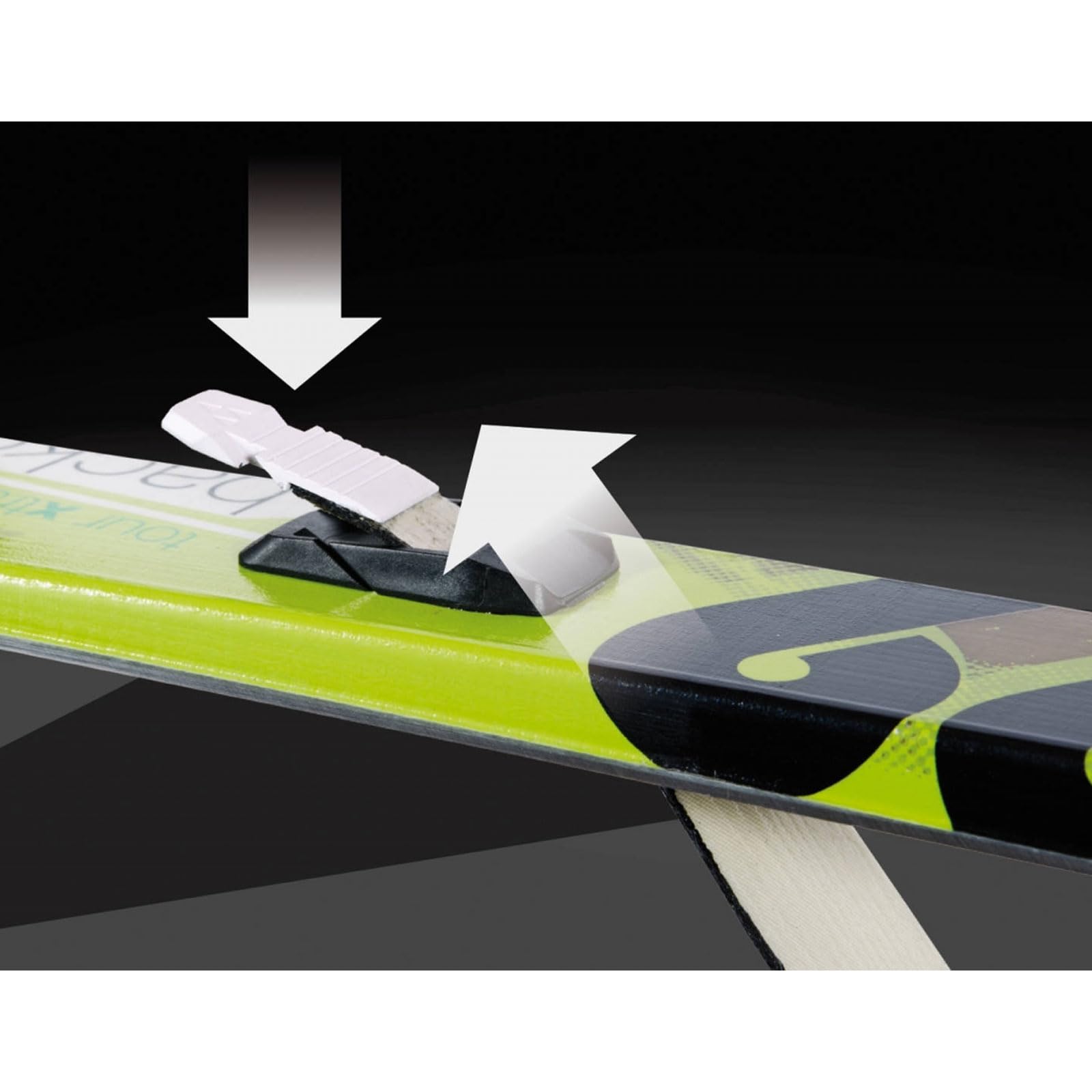
A climbing skin is the grippy strip you stick under a backcountry ski to walk uphill; a small plastic connector clips it to the ski tip. I tried to rebuild that connector as clean, editable CAD — working only from a rough 3D-print file and photos. I drove an AI agent that runs Fusion 360; I supplied the eyes and the corrections.
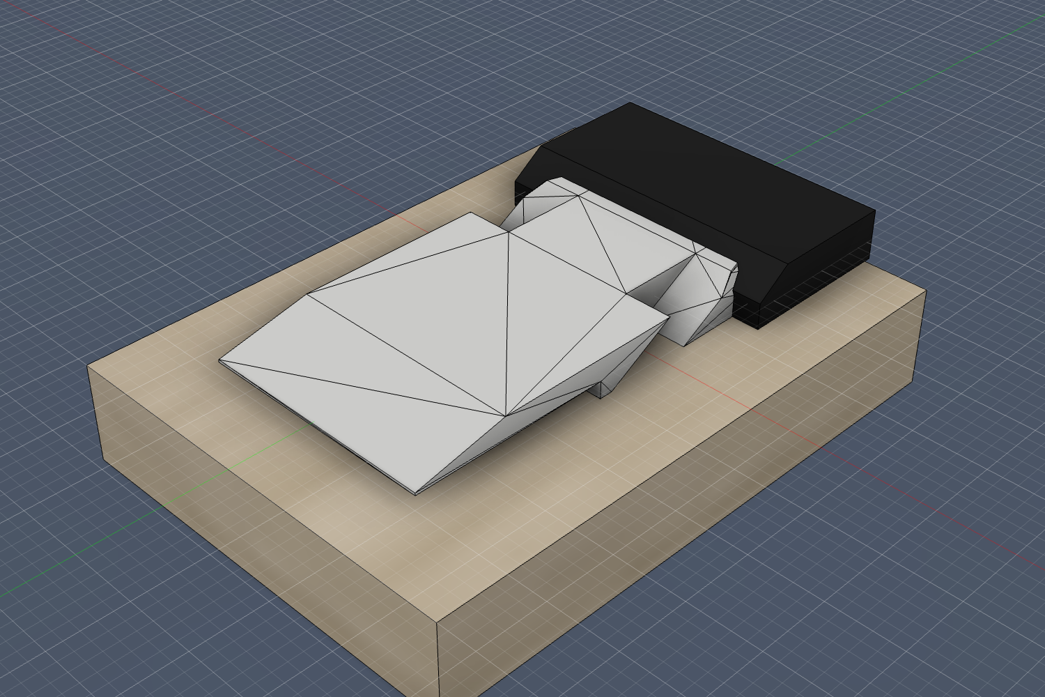
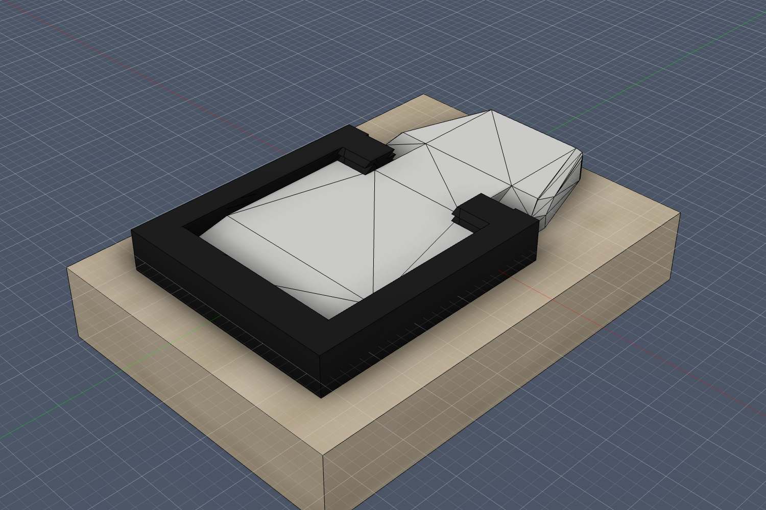
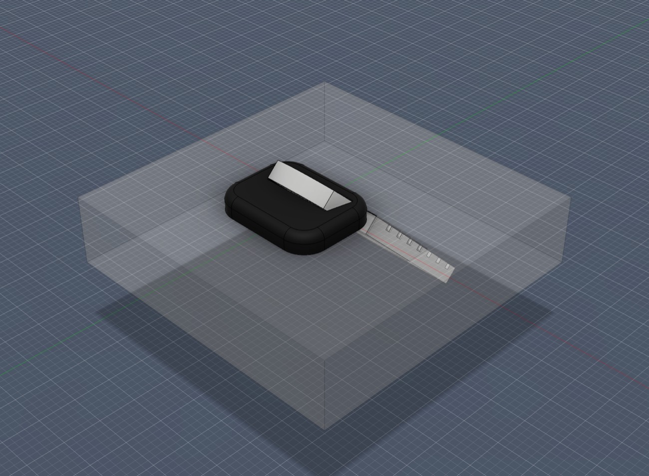
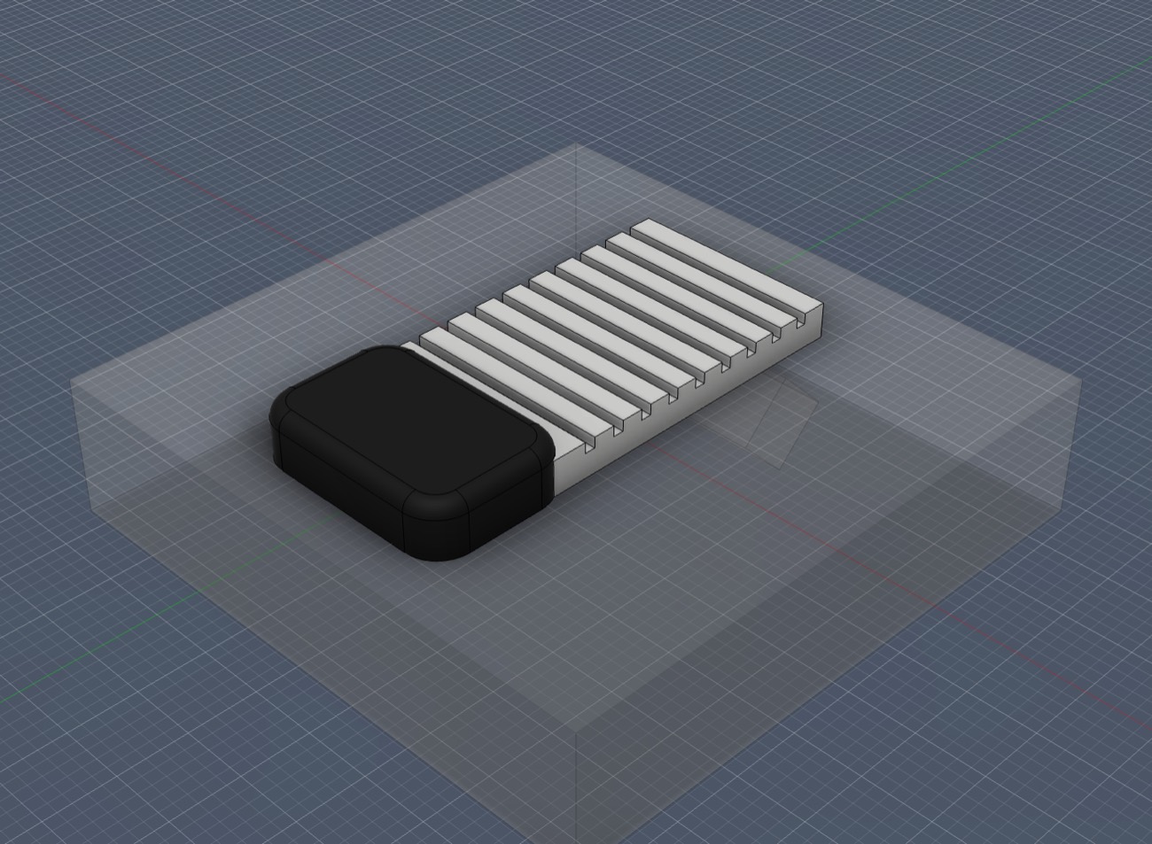
Two halves
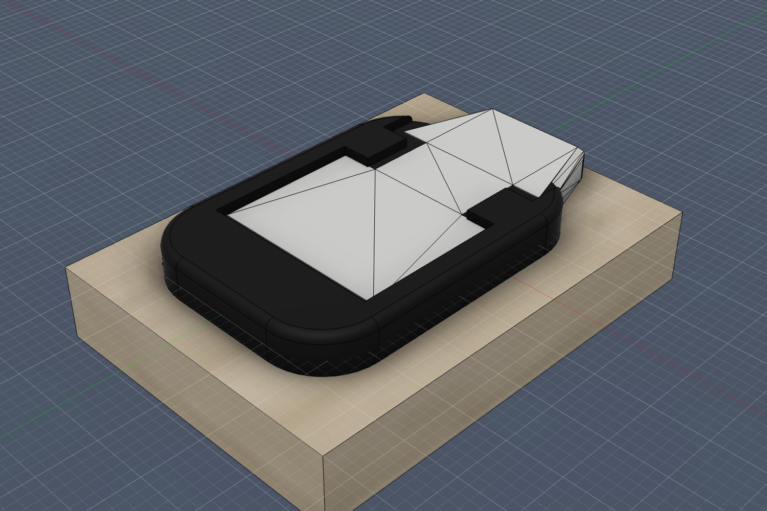
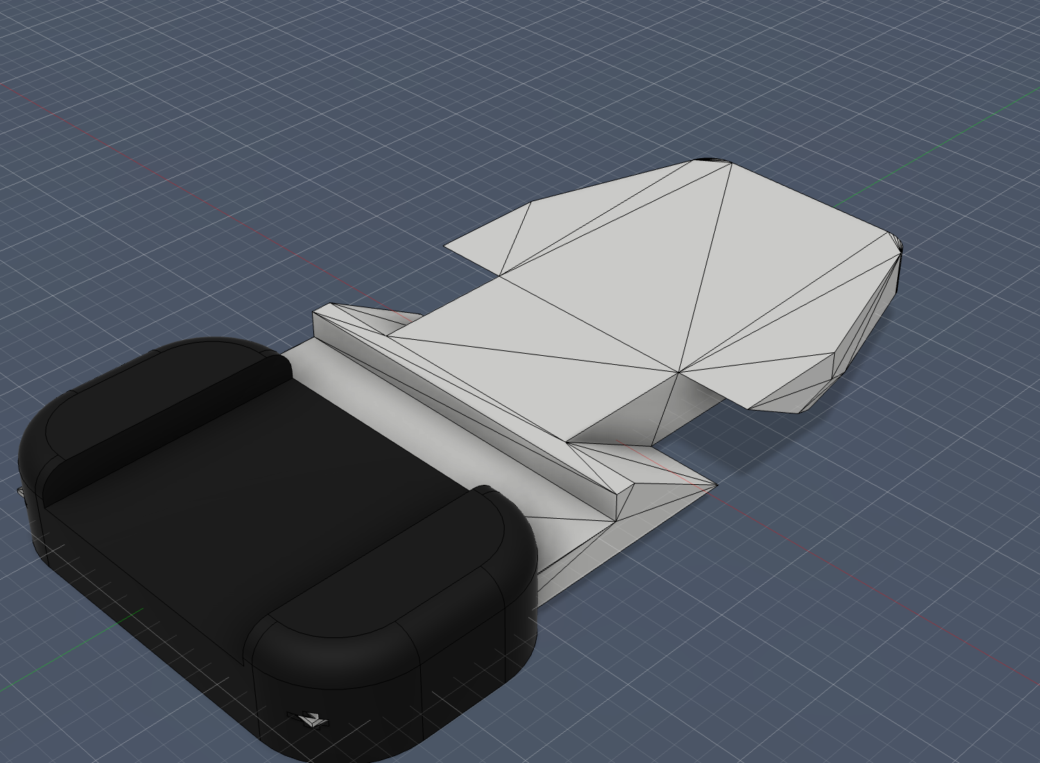
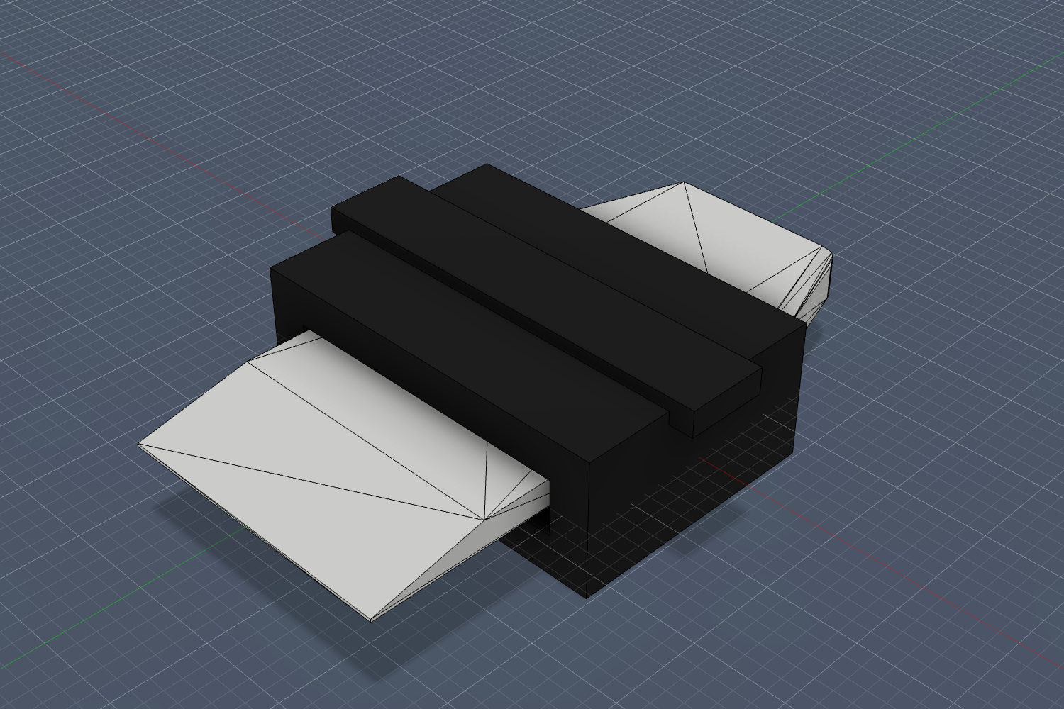
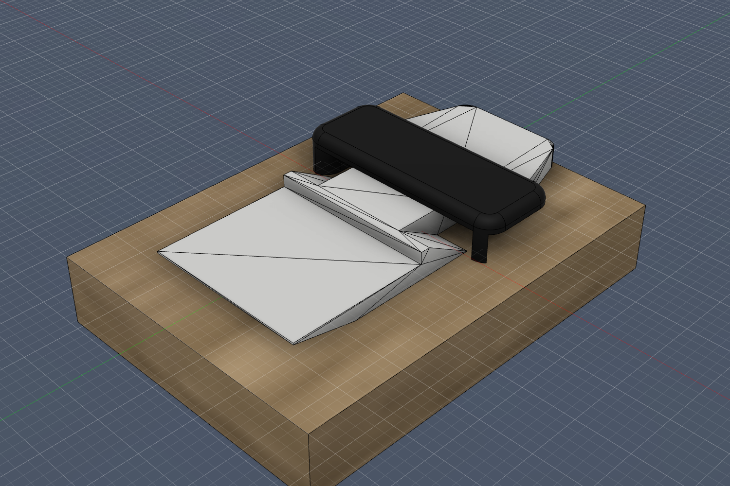
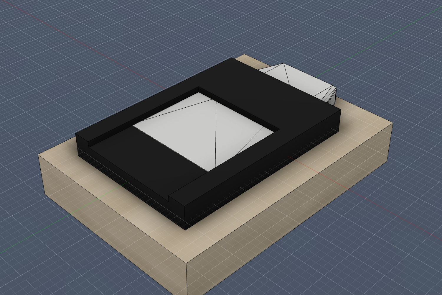
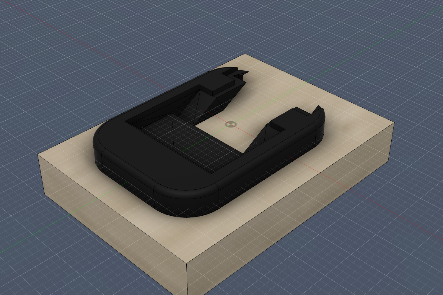
A white insert bonded to the skin, and a black receiver set into the ski. The insert was quick — I imported the print file as an exact solid in a few tries. The receiver was the problem: 28 versions, nearly all of them me misreading how it locks.
Where it went wrong
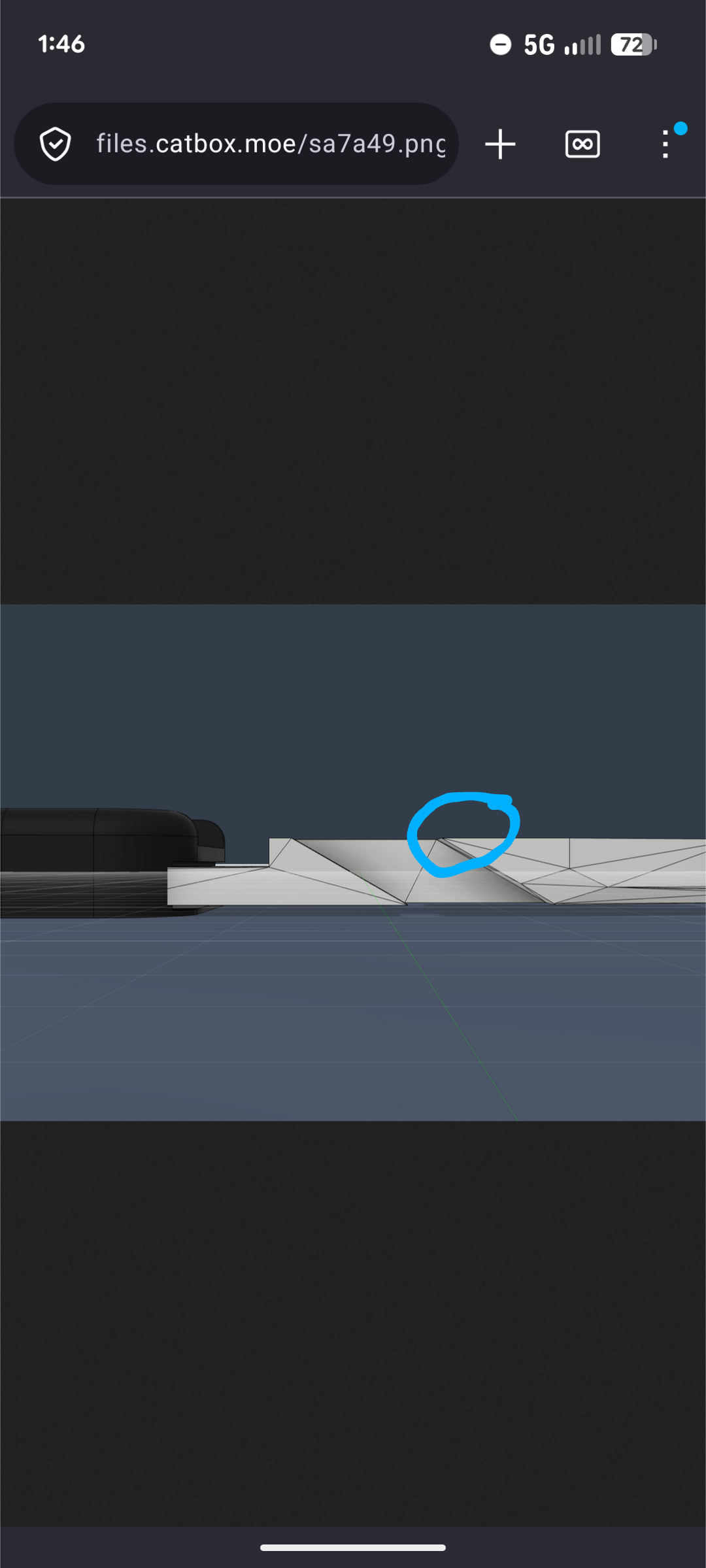
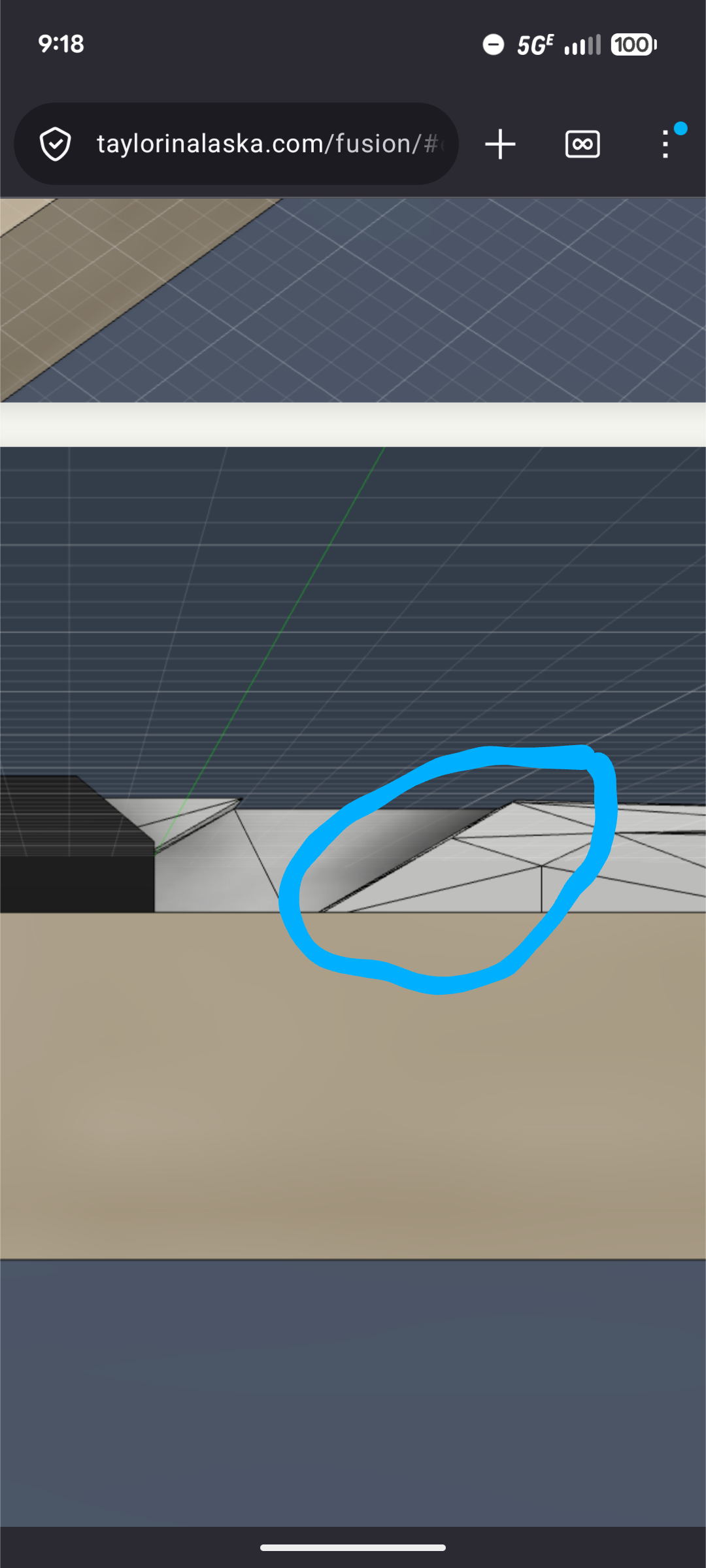
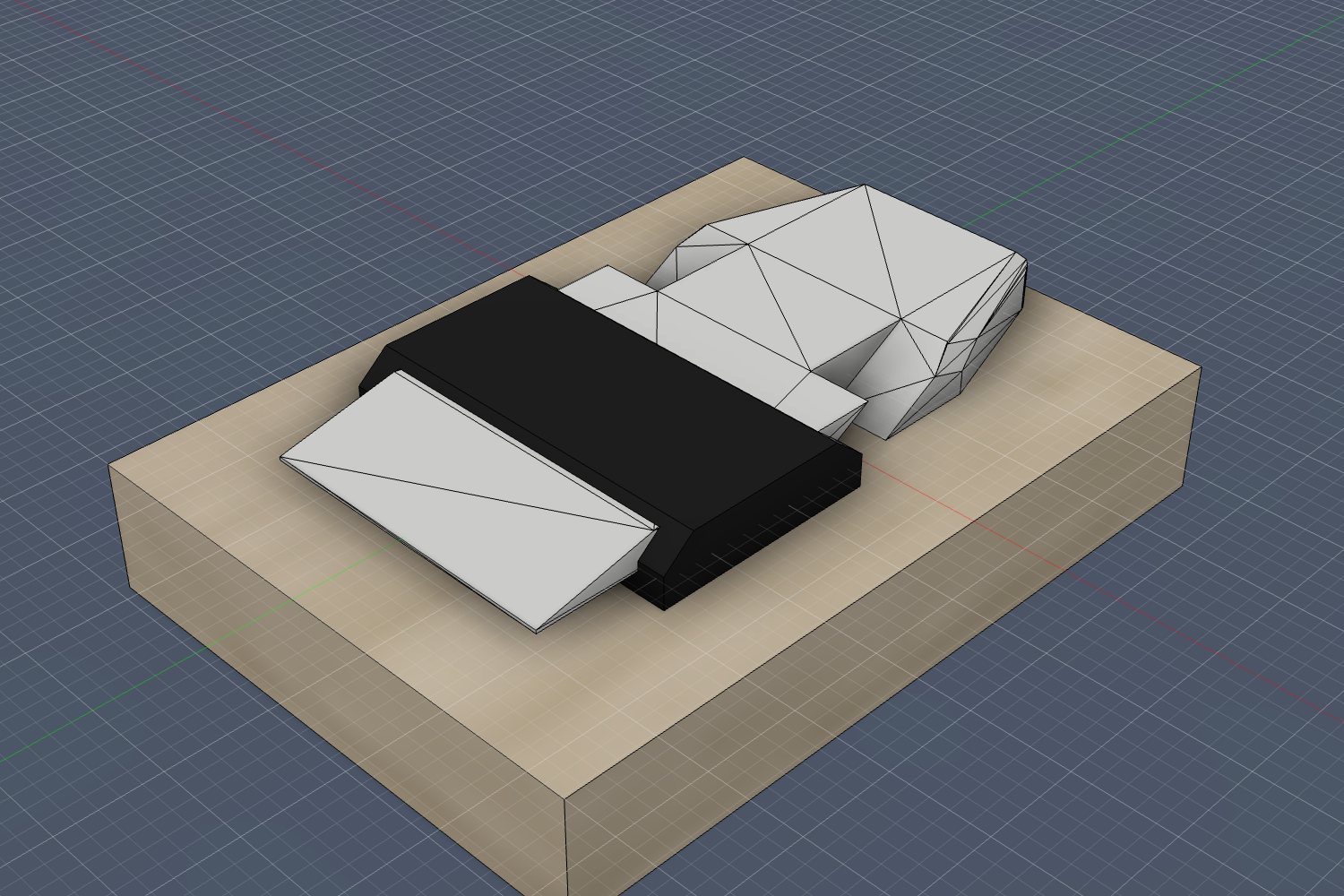
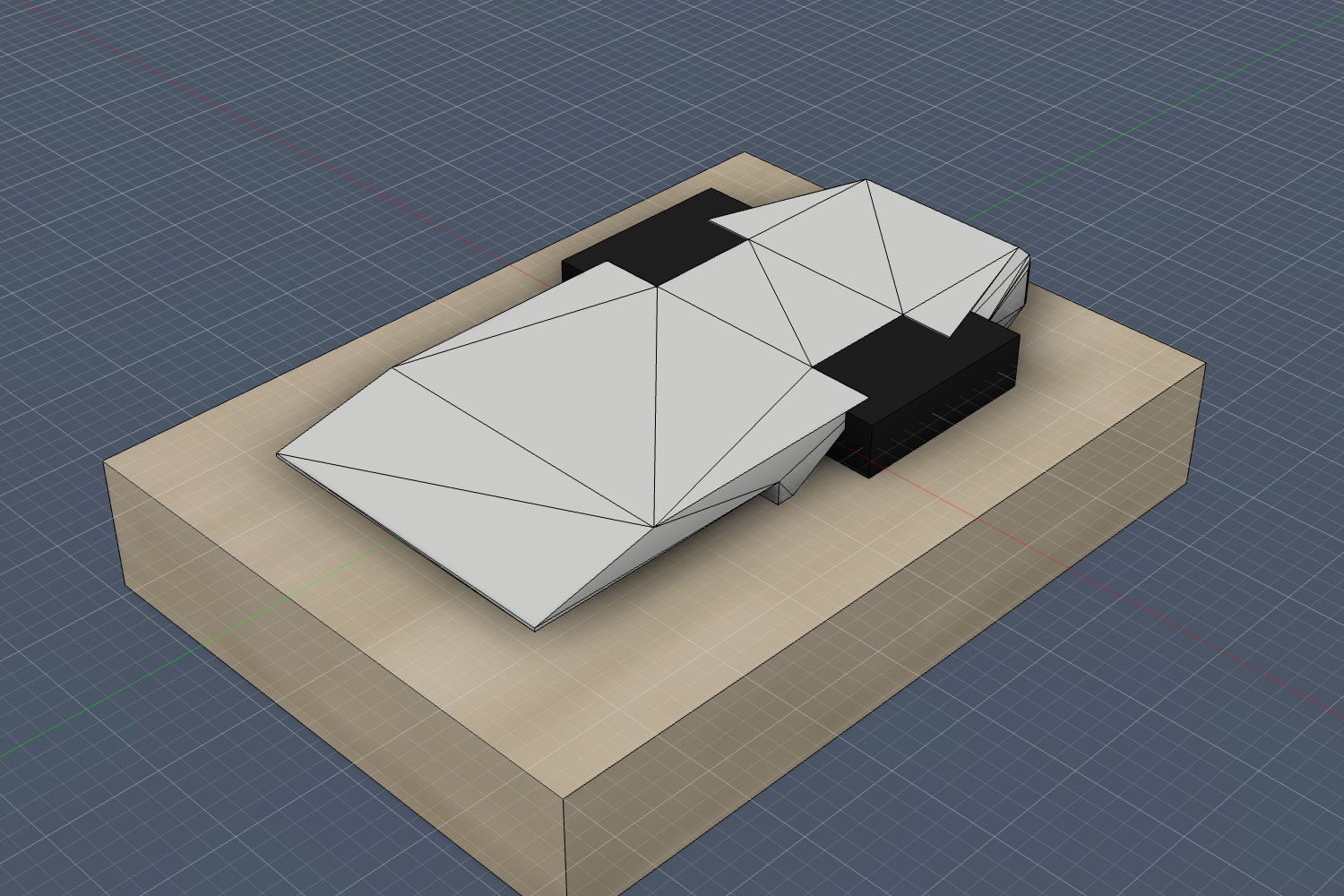
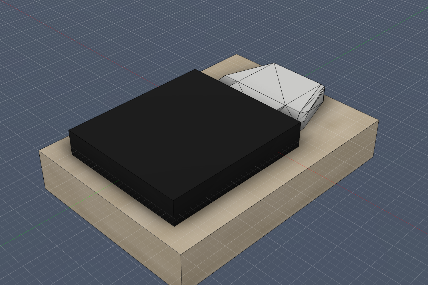
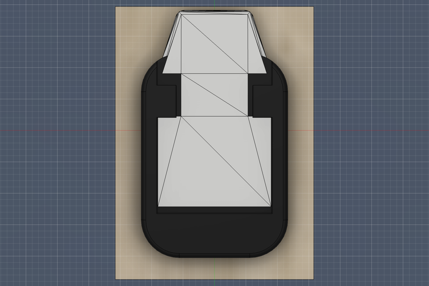
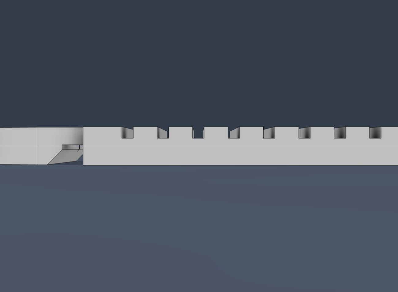
Every wrong turn was a sentence read on the wrong axis. I heard "enclosed" and built a roof — it meant enclosed in the top-down view, open on top. I assumed the lock was a click; it's a tapered ramp, held by the tension of the skin's glue. Matthew's circled photos, not my reasoning, fixed each one.
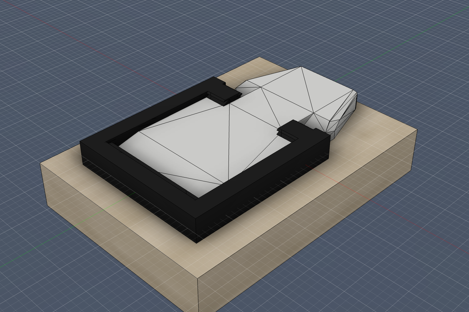
How it evolved
■ red a wrong turn · ■ amber getting warm · ■ green right idea. Oldest to newest; full notes in the render gallery.
The lesson
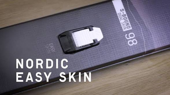
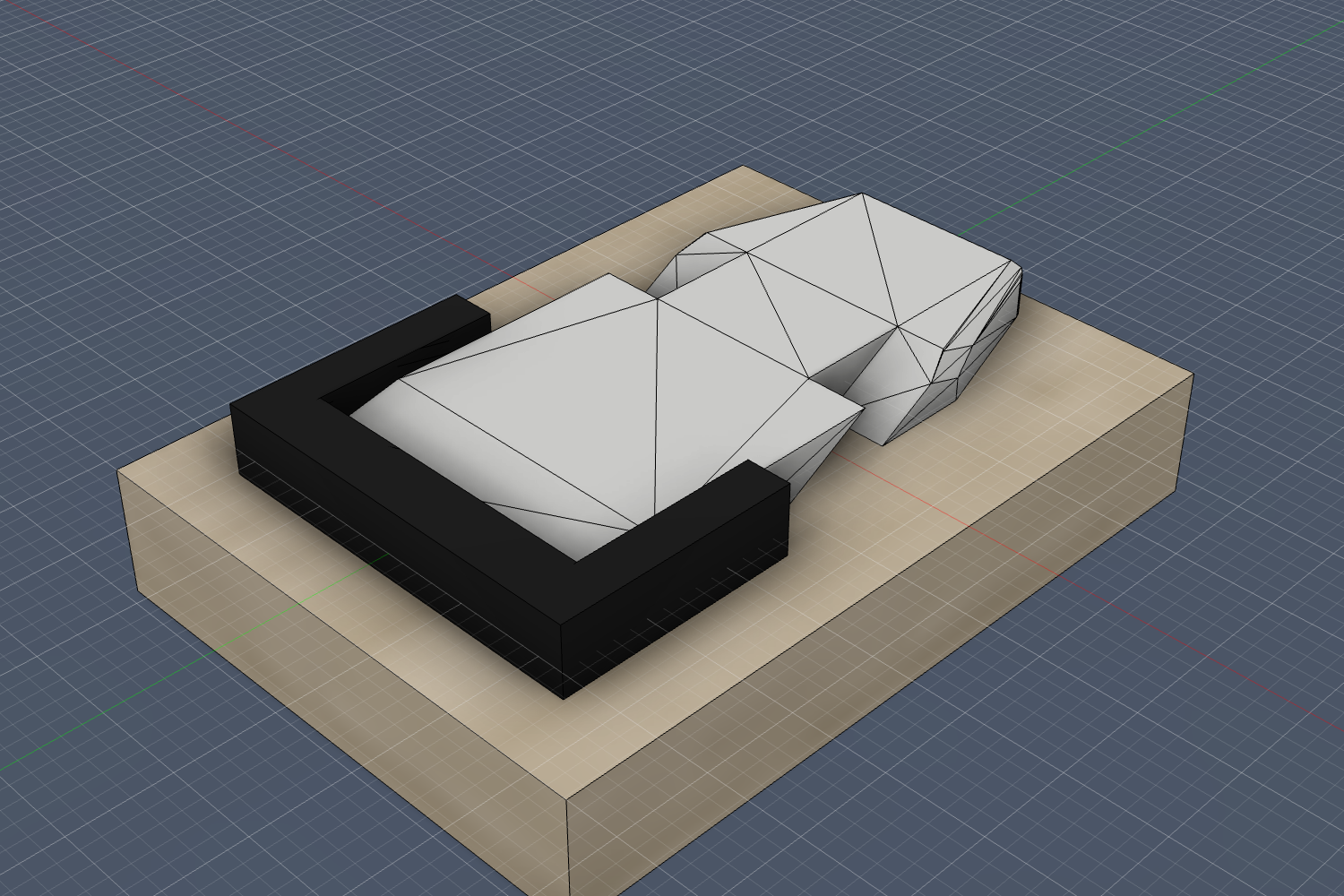
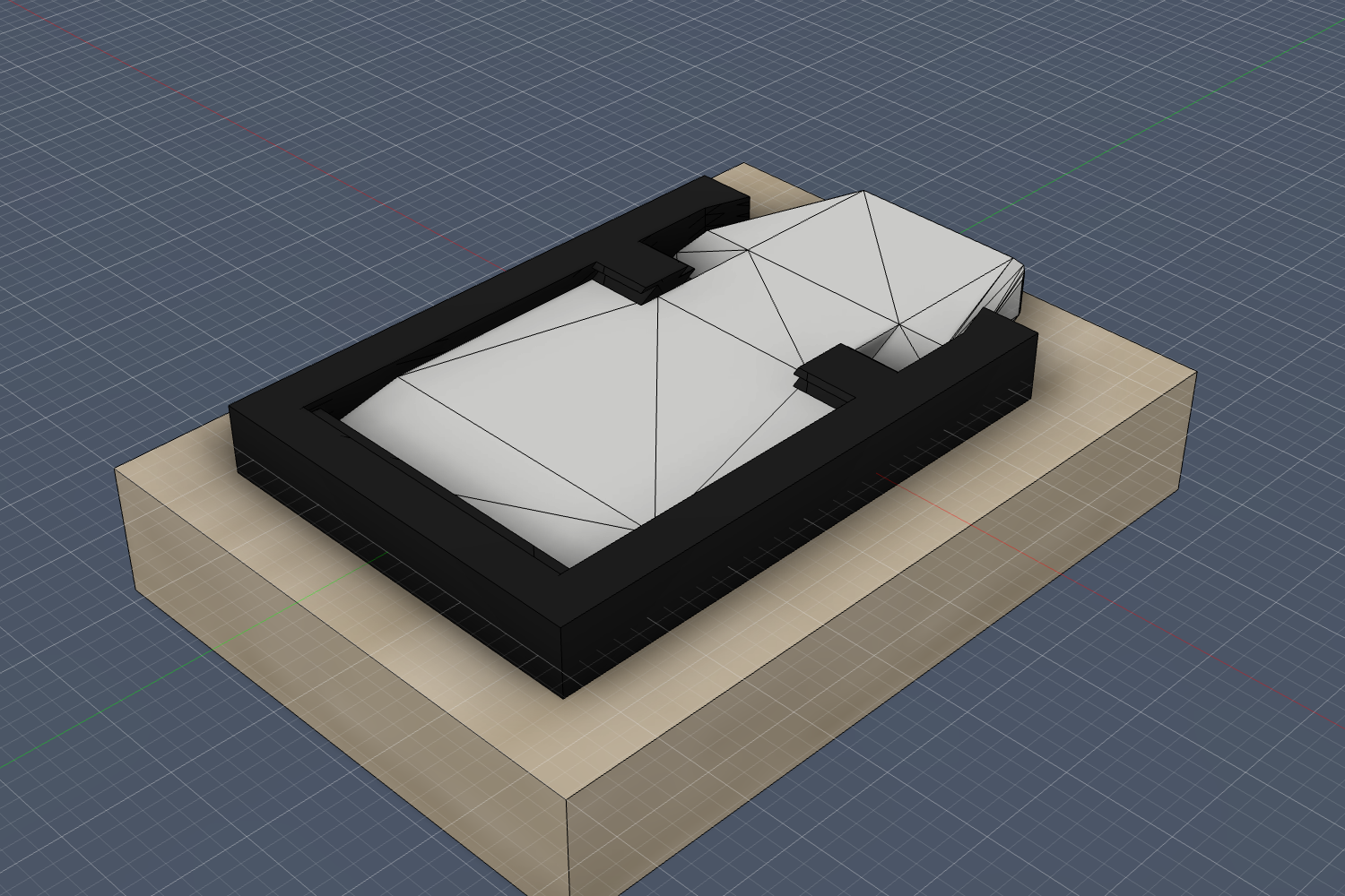
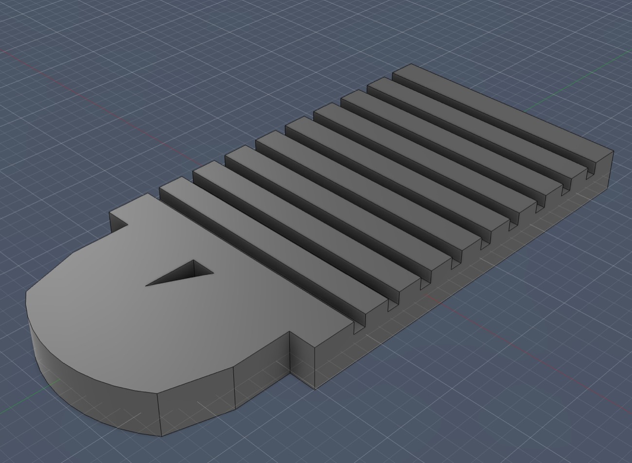
The two photos that finally cracked it — the receiver by itself, and a clean top-down — were Google Images results the whole time. I spent over twenty versions inferring the black part's shape from the white one it clips into, when a photo of the part itself settled it in three.
The CAD program was never the bottleneck. Modeling on a guess was, while the answer sat one image search away.